Tinggalkan Pesan
Jika Anda tertarik dengan produk kami dan ingin mengetahui detail lebih lanjut, silakan tinggalkan pesan di sini, kami akan membalas Anda sesegera mungkin.

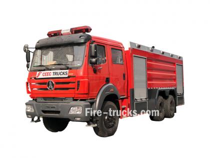
The fire truck PTO (Power Take-Off) is a power transmission device that transfers engine power to the fire pump. When the firefighter activates the PTO, mechanical power from the engine is transmitted through the transmission and PTO to the fire pump — this is the core working principle of how a fire fighting truck PTO system operates — enabling the pump to deliver high-pressure, high-flow water or foam without the need for a separate auxiliary engine.
Modern fire trucks typically use side-mounted PTO or full power PTO systems. These offer stable power output, convenient operation, and low maintenance costs, making them an essential component of the fire truck's firefighting system.
 Work")
PTO (Power Take-Off) is a critical component in the fire truck's power system. It is a gear transmission device installed between the engine and the transmission, designed to "divert" a portion of mechanical power from the vehicle's engine or transmission to the fire pump or other auxiliary equipment, without affecting the vehicle's normal driving capability.
The fire truck engine is originally responsible only for driving the wheels. However, once the fire truck arrives at the fire scene, the wheels no longer need power, while the fire pump requires power to draw and pressurize water. The PTO is the device that accomplishes this "power switch."

Power Take-Off (PTO) literally means "power output device."
On a fire truck, it refers to extracting rotational power from the engine flywheel or transmission gears through gear engagement, and delivering it to the fire pump or other auxiliary equipment.
Its name describes its function:
Engine = Power source
PTO = Power distributor
Fire pump = Power consumption end
Therefore, the PTO is the bridge connecting the "power source" and the "firefighting system."
The core reason fire trucks must be equipped with a PTO is that firefighting operations require continuous, stable, high-power output that cannot rely on the vehicle's driving state.
Main reasons:
1. Provides continuous firefighting power
The fire pump needs to run for extended periods during firefighting operations. The PTO allows the engine to continuously drive the fire pump at idle or fixed RPM, ensuring stable water pressure and flow.
2. Improves power utilization efficiency
Without a PTO, a separate auxiliary engine would be required to drive the fire pump, which would increase:
Cost
Maintenance complexity
Risk of failure
Space occupation
The PTO directly utilizes the vehicle's engine power, improving overall efficiency.
3. Supports multiple firefighting systems
Modern industrial fire trucks may include not only water pumps but also:
Foam systems
Dry powder systems
High-pressure water systems
Remote-controlled fire monitors
Without a PTO, there are only two solutions:
Install a separate engine to drive the pump → increases weight, cost, maintenance points, and occupies space
Keep the pump permanently connected to the transmission → pump stops when vehicle stops, unable to pump water on site
The PTO solves both problems at once:
| Mode | PTO Status | Power Destination | Result |
| Driving mode | Disengaged | All to wheels | Normal driving |
| Firefighting mode | Engaged | All to fire pump | Pumping while stationary |
The PTO is essentially a "power distribution and conversion system" that transforms vehicle driving power into firefighting operational power.
From an engineering perspective, the complete power path is:
Engine → Transmission → PTO → Drive Shaft → Fire Pump → Fire Monitor/Hose System
The PTO's working principle can be summarized in three key stages: power take-off, engagement, and transmission.
The PTO draws power from the engine. Depending on the installation position, the power take-off method differs:
| PTO Type | Installation Position | Power Source | Characteristics |
| Side-mounted PTO | Transmission side | Transmission countershaft gear | Simple structure, lower power (≤50% engine power) |
| Sandwich PTO | Between engine and transmission | Engine flywheel | Full power output, mainstream configuration |
| Split-shaft PTO | Between transmission and driveshaft | Transmission output shaft | High power, allows pumping while driving |
After the driver presses the PTO switch in the cab, the engagement mechanism activates:
| Engagement Method | Working Principle | Common On |
| Electric solenoid control | Electrical signal activates solenoid, pushing shift fork | Mainstream on modern fire trucks |
| Pneumatic control | Compressed air pushes piston, actuating fork | Large fire trucks |
| Manual cable | Mechanical cable directly pulls fork | Older vehicles |
Operation sequence:
Press PTO switch → Solenoid/cylinder actuates → Shift fork pushes sliding gear → Meshes with flywheel or transmission gear → Power connected
After the PTO output shaft begins rotating, power is transmitted through the drive shaft to the fire pump:
PTO output shaft rotates → Drive shaft → Fire pump input shaft → Pump impeller rotates → Water is pressurized and discharged
| Step | Action | Result |
|---|---|---|
| Step 1 | Engine starts, vehicle idling or driving | Engine running, PTO disengaged |
| Step 2 | Arrive at scene, driver presses PTO switch | Driving power disengaged (on some models), PTO gear activated |
| Step 3 | PTO establishes power connection with transmission | Transmission power is diverted to PTO output shaft |
| Step 4 | Drive shaft transmits power to fire pump | Fire pump begins receiving continuous mechanical power |
| Step 5 | Fire pump impeller rotates at high speed | Suction → Pressurization → Delivery to discharge lines → Firefighting |
| Step 6 | System reaches balanced RPM | Stable output, adjustable pressure, flow, and spray pattern |
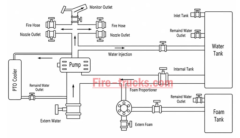
The fire truck PTO system is a complete power transmission chain, with multiple components working together to transfer engine power to the fire pump. The system can be broken down into six core components:
The engine is the power source of the PTO system and the heart of the entire fire truck.
Function: Generates raw rotational power, driving the flywheel or crankshaft.
Power output: Typically 300–600 HP (depending on chassis model and configuration).
Relationship with PTO: The PTO draws power from the engine flywheel or crankshaft — it is the starting point of power.
Key characteristic: Engine RPM directly affects PTO output speed and the fire pump's water discharge capability. Fire trucks are typically equipped with high-power diesel engines, which not only drive the vehicle but also provide ample power reserve for the fire pump. After PTO engagement, the operator can control pump discharge pressure by adjusting engine RPM.
The transmission is responsible for power delivery and speed matching.
Function: Receives engine power and adjusts speed and torque through different gear combinations.
Relationship with PTO: Side-mounted PTO draws power from internal transmission gears; sandwich PTO is installed at the front of the transmission.
Key characteristic: Transmission gear position does not affect PTO output speed — PTO operates independently of gear selection.
Two power take-off positions:
Transmission side window take-off: PTO mounted on transmission side, drawing power from countershaft or intermediate shaft gears; common on medium-duty fire trucks.
Transmission rear-end take-off (sandwich): PTO installed between engine and transmission, drawing power directly from the flywheel, enabling full power output.
The PTO is the core of the entire system, responsible for "extracting" power from the engine and delivering it to the fire pump.
Function: Extracts power from the engine or transmission and converts it to the speed and torque suitable for the fire pump.
Installation position: Transmission side (side-mounted) or between engine and transmission (sandwich).
Key characteristic: Determines power transmission efficiency, speed matching, and operational convenience.
The drive shaft is the "power bridge" connecting the PTO and the fire pump.
Function: Transmits rotational power from the PTO output shaft to the fire pump input.
Structure: Typically consists of a metal shaft tube, universal joints, and splined connections.
Key characteristic: Must be precisely aligned to avoid vibration; universal joints allow angular compensation.
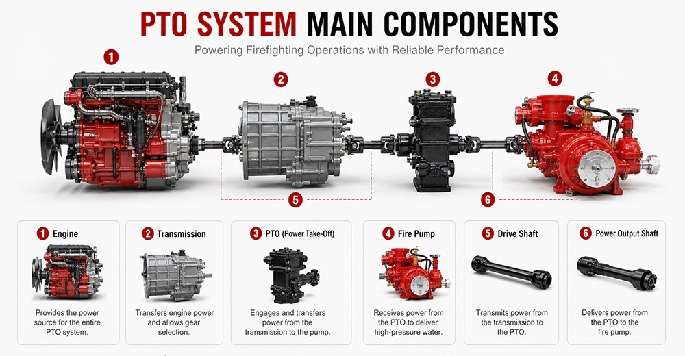
The fire pump is the final load of the PTO system, responsible for converting mechanical energy into water pressure energy.
Function: Receives rotational power from the PTO, drives the impeller to rotate, draws water in, and discharges it under high pressure.
Type: Centrifugal pump (single-stage, two-stage, or multi-stage).
Typical flow rate: 20 L/s – 180 L/s (1,200 – 6,000 L/min).
Typical pressure: 1.0 – 2.5 MPa (10 – 25 bar).
The PTO control system is the "command center" between the driver and the PTO system, responsible for engagement, disengagement, safety protection, and status indication.
Function: Controls PTO engagement and disengagement, monitors system status, and provides safety protection.
Operating location: Cab interior (primary control) and pump panel (auxiliary control).
Control methods: Manual cable, electric solenoid, pneumatic.
Specific control functions:
(1) PTO Engagement Control
The operator presses the PTO switch (electric solenoid/pneumatic) or pulls the lever (manual) in the cab. The control system sends a signal to engage the PTO's internal gears with the power source. After successful engagement is confirmed, an indicator light illuminates, allowing the operator to increase engine RPM.
(2) PTO Disengagement Control
The operator presses the switch again or resets the lever. The control system cuts the signal, and the PTO gears disengage. After disengagement is confirmed, the indicator light turns off.
| PTO Type | Installation Position | Power Source | Power Output | Typical Application |
| Sandwich PTO | Between engine and transmission | Engine flywheel | Full power (≥90%) | Fire pumpers, aerial trucks |
| Split-shaft PTO | Middle of chassis driveshaft | Transmission output shaft | Full power | Large vacuum trucks, airport fire trucks |
| Side-mounted PTO | Transmission side | Transmission gears | Partial power (lower) | Sprinkler trucks, small vacuum trucks |
Sandwich PTO
Advantages: Full power output (≥90%), supports "pumping while driving" (dual-function), high transmission efficiency, easy lubrication.
Disadvantages: Higher cost, complex installation, requires modification to the engine-transmission connection.
Split-shaft PTO
Advantages: Full power output, no additional space required, high reliability, good dynamic balance, can replace auxiliary engine to drive large pumps.
Disadvantages: Requires cutting the original driveshaft, installation position selection must consider driveshaft angle and length compensation.
Side-mounted PTO
Advantages: Low cost, simple installation, can draw power directly from the transmission side.
Disadvantages: Only partial power available, lower output torque, cannot drive high-power fire pumps, mainly used for low-speed, low-power equipment.
 for Fire Trucks")
The process follows a clear mechanical transmission chain:
Engine → PTO → Drive Shaft → Fire Pump → Impeller Rotation → Suction → Pressurization → Fire Monitor
| Factor | Role |
|---|---|
| Centrifugal pump characteristic | When impeller speed is constant, discharge pressure remains naturally stable |
| PTO rigid connection | No slippage or power loss, ensuring continuous stable power input |
| Pressure governor | Automatically detects flow changes and adjusts engine RPM to maintain set pressure |
| Relief valve | Automatically bypasses when pressure exceeds limit, preventing equipment damage |
① Pump speed is determined by engine RPM
Fire pump impeller speed = Engine RPM × PTO ratio. The PTO ratio is fixed (e.g., 1.75:1), so pump speed changes directly with engine RPM.
Calculation formula:
Engine RPM × PTO ratio = Pump speed (RPM)
② Physical relationship between pressure and speed
The pressure generated by a centrifugal pump is proportional to the square of the impeller speed. This physical law means that small changes in RPM cause significant pressure fluctuations.
Speed increases → Centrifugal force increases → Discharge pressure rises
Speed decreases → Centrifugal force decreases → Discharge pressure drops

1. PTO will not engage
Possible causes: Low air pressure (pneumatic type), faulty solenoid, damaged or stuck cable, interlock conditions not met (parking brake not applied, transmission not in neutral).
Solutions: Check air system pressure (must be ≥0.6 MPa); test solenoid; inspect cable; confirm parking brake is applied and transmission is in neutral.
2. PTO engages but pump does not work
Possible causes: PTO clutch failure, broken drive shaft or worn splines, damaged internal gears.
Solutions: Check PTO clutch engagement; inspect drive shaft for breakage or loose connections; disassemble and inspect internal gears.
3. PTO unusual noise
Possible causes: Poor gear meshing or wear, worn bearings, insufficient or degraded lubrication, PTO not fully disengaged.
Solutions: Check gear clearance and tooth wear; inspect bearings; replace with qualified lubricant; confirm PTO is fully disengaged.
4. PTO oil leakage
Possible causes: Worn or deteriorated seals, cracked housing, loose mounting bolts.
Solutions: Replace seals (O-rings, oil seals); inspect housing for cracks; tighten mounting bolts.
5. PTO overheating
Possible causes: Prolonged high-load operation, insufficient or degraded lubricating oil, cooling system failure.
Solutions: Reduce load or shut down for cooling; replace with qualified lubricant; inspect cooling lines.
6. PTO insufficient power
Possible causes: Improper PTO ratio selection, engine RPM set too low, clutch slippage.
Solutions: Confirm PTO ratio matches the fire pump; increase engine RPM to rated operating range; inspect clutch for slippage.
Q1. What does PTO stand for on a fire truck?
PTO stands for Power Take-Off. It is a mechanical system that transfers engine power from the truck's transmission to the fire pump. In simple terms, PTO allows the fire truck's engine to power the pumping system so it can deliver high-pressure water or foam for firefighting operations without needing a separate engine. It is a critical component in industrial and municipal fire trucks.
Q2. Why do fire trucks need a PTO?
Fire trucks need a PTO because it enables the vehicle's main engine to drive the fire pump efficiently. Without a PTO, the fire pump would require a separate engine, which increases cost, weight, and maintenance complexity. PTO systems provide a compact, reliable, and fuel-efficient way to ensure continuous water or foam supply during firefighting operations.
Q3. Can a fire truck operate without a PTO?
Most modern fire trucks cannot operate their pumping system without a PTO because the PTO is responsible for transferring engine power to the fire pump. However, some specialized fire vehicles may use an independent auxiliary engine to drive the pump. These designs are less common due to higher cost, increased maintenance, and lower efficiency compared to PTO-based systems.
Q4. What is the difference between PTO and a fire pump?
The PTO is a power transmission device, while the fire pump is a water or foam pumping system. The PTO delivers mechanical power from the engine to the pump, and the fire pump converts that power into hydraulic pressure to move water or foam. In short, PTO is the "power source connector," and the fire pump is the "firefighting output device."
Q5. How much power can a fire truck PTO provide?
The power output of a fire truck PTO depends on the vehicle design and transmission system. Typically, PTO systems can provide between 50 kW to over 300 kW of mechanical power. Heavy-duty industrial and airport fire trucks often use high-capacity PTO systems capable of supporting large-flow fire pumps and continuous high-pressure operations.
Q6. What are the different types of fire truck PTOs?
There are several types of fire truck PTO systems, including side-mounted PTO, rear-mounted PTO, split shaft PTO, and full power PTO. Side-mounted PTO is commonly used in standard fire trucks, while split shaft and full power PTO systems are used in industrial and airport fire trucks where higher power output and continuous operation are required.
Q7. How do you maintain a fire truck PTO?
PTO maintenance includes regular inspection of lubrication oil levels, checking for leaks, tightening mounting bolts, and ensuring proper alignment of the drive shaft. Operators should also test engagement and disengagement functions regularly. Preventive maintenance is essential to avoid overheating, mechanical wear, and unexpected failure during emergency operations.
Q8. What causes a fire truck PTO to fail?
Common causes of PTO failure include insufficient lubrication, worn gears, misalignment of the drive shaft, overheating, and improper operation by the driver. Electrical or hydraulic control system failures can also prevent PTO engagement. Regular maintenance and correct operating procedures significantly reduce the risk of PTO failure.
Q9. Which PTO is best for industrial fire trucks?
For industrial fire trucks, the best option is usually a split shaft PTO or full power PTO system. These systems can handle high power output, continuous operation, and large-capacity fire pumps. They are widely used in petrochemical plants, refineries, airports, and large industrial facilities where reliable and long-duration firefighting performance is required.
Q10. What should buyers consider when choosing a fire truck PTO?
Buyers should consider engine power compatibility, required fire pump flow rate, vehicle type, and working environment. It is also important to evaluate PTO durability, cooling performance, maintenance accessibility, and compatibility with the chassis. For export projects, compliance with international standards and local regulations should also be taken into account to ensure approval and operational reliability.
PTO (Power Take-Off) is the core system that transfers engine power to the fire pump — it determines whether the entire firefighting system can operate properly.
The fire truck power chain is: Engine → Transmission → PTO → Drive Shaft → Fire Pump → Fire Monitor. Any weak link in this chain affects final firefighting performance.
The primary function of the PTO is to provide stable, continuous mechanical power output, enabling the fire truck to deliver efficient water or foam supply without requiring a separate engine.
Different PTO types (Side-mounted, Rear-mounted, Split shaft, Full power) are suited to different fire truck classes. Industrial fire trucks typically prioritize high-power PTO systems.
PTO performance must match the fire pump flow rate and vehicle chassis, otherwise issues such as insufficient power, unstable pressure, or system overload may occur.
Regular PTO system maintenance (lubrication, tightening, alignment inspection) is key to ensuring reliable fire truck operation, especially in high-intensity industrial applications.
When purchasing industrial fire trucks, buyers should not focus solely on price. PTO power, stability, compatibility, and after-sales support are equally critical factors to evaluate.
For high-risk scenarios such as petrochemical plants, airports, and large industrial parks, Full Power PTO or Split Shaft PTO systems are recommended to ensure continuous operational capability.


Anda mungkin tertarik dengan informasi berikut
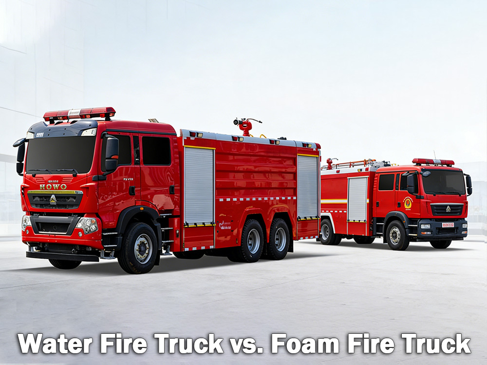
Truk pemadam kebakaran air Mobil pemadam kebakaran busa memadamkan kebakaran biasa yang melibatkan kayu, kertas, dan kain. Mobil pemadam kebakaran busa memadamkan kebakaran cairan yang mudah terbakar seperti bensin dan minyak. Mana yang tepat bergantung pada bahaya yang ada. A truk pemadam kebakaran air Truk pemadam kebakaran ini membawa tangki air besar dan mengandalkan pompa bertekanan tinggi untuk menyalurkan air melalui selang atau meriam dek. Ini adalah jenis truk pemadam kebakaran yang paling umum digunakan oleh departemen pemadam kebakaran kota dan lokasi industri di seluruh dunia. A mobil pemadam kebakaran busa Di sisi lain, pesawat ini dirancang khusus untuk membawa dan menyemprotkan busa pemadam kebakaran. Ketika air saja tidak dapat memadamkan api secara efektif — seperti pada cairan yang mudah terbakar, bahan kimia, atau kebakaran bahan bakar — busa adalah pilihan yang lebih baik. Busa bekerja dengan menciptakan lapisan di atas api, memutus pasokan oksigen dan mencegah penyalaan kembali. I. Apa Itu Mobil Pemadam Kebakaran Air? Truk pemadam kebakaran air adalah kendaraan yang dilengkapi dengan tangki air besar, pompa yang kuat, dan selang atau monitor untuk menyalurkan air ke lokasi kebakaran. Tangki air biasanya menampung antara 500 hingga 3.000 galon (sekitar 2.000 hingga 12.000 liter). Pompa menarik air dari tangki atau dari sumber eksternal seperti hidran kebakaran, danau, atau kolam, kemudian mendorongnya melalui selang dengan tekanan tinggi. Di mana truk pemadam kebakaran air paling efektif: Mobil pemadam kebakaran air sangat ideal untuk Kebakaran Kelas A , yang melibatkan bahan bakar biasa: Kayu dan papan kayu Kertas dan karton Kain dan bahan Karet dan plastik Rumput, semak, dan material hutan Jika api melibatkan bahan yang mudah terbakar di rumah, gudang, atau ladang, air biasanya dapat memadamkannya. Keterbatasan air: Air memiliki satu kelemahan utama. Ketika disemprotkan pada cairan yang terbakar seperti bensin, minyak, atau bahan kimia, air akan tenggelam karena lebih berat daripada bahan bakar tersebut. Bahan bakar akan mengapung di atas dan terus terbakar. Dalam beberapa kasus, air bahkan dapat menyebarkan api ke area yang lebih luas. Itulah mengapa air saja tidak efektif untuk memadamkan kebakaran cairan yang mudah terbakar. Spesifikasi pompa air truk pemadam kebakaran: Mobil pemadam kebakaran air monitor kebakaran Spesifikasi: II. Apa Itu Mobil Pemadam Kebakaran Busa? Truk pemadam kebakaran busa adalah kendaraan khusus yang dirancang untuk mengangkut dan mengirimkan busa pemadam kebakaran. Kendaraan ini membawa dua tangki terpisah — satu untuk air dan satu untuk konsentrat busa. Sistem pencampuran busa mencampur keduanya dengan rasio tertentu, biasanya 1%, 3%, atau 6% konsentrat busa terhadap air. Campuran ini kemudian melewati nosel busa tempat udara ditambahkan, menciptakan lapisan busa yang mengembang dan stabil. Cara kerja busa: Busa tersebut membentuk lapisan di atas cairan atau material yang terbakar. Selimut ini: ...
Detail
Mobil pemadam kebakaran Beroperasi melalui fungsi terkoordinasi dari berbagai sistem untuk mencapai pasokan air, pembangkitan tekanan, dan pemadaman kebakaran. Memahami prinsip-prinsip ini membantu petugas pemadam kebakaran beroperasi secara efektif dalam situasi darurat. » I. Cara Kerja Mobil Pemadam Kebakaran: ▪ A. Sistem Pompa: Jantung Pemadam Kebakaran: Jantung dari setiap truk pemadam kebakaran adalah pompanya. Unit bertenaga tinggi ini menarik air dari tangki di dalam truk atau sumber eksternal—seperti hidran kebakaran, danau, atau kolam—dan menyalurkannya melalui selang di bawah tekanan tinggi. Pompa yang paling umum digunakan adalah pompa sentrifugal, yang mengandalkan impeler yang berputar untuk memberi tekanan dan menggerakkan air. Petugas pemadam kebakaran mengendalikan aliran air menggunakan serangkaian tuas dan pengukur pada panel pompa. Mereka dapat menyesuaikan tekanan sesuai kebutuhan dan mengarahkan air ke beberapa saluran selang secara bersamaan. Jenis Pompa Karakteristik Aplikasi Terbaik Pompa sentrifugal satu tahap Aliran tinggi, tekanan sedang Pemadam kebakaran umum kota Pompa sentrifugal dua tahap Dapat beralih antara volume dan tekanan. Gedung-gedung tinggi, selang-selang panjang terbentang Pompa multi-tahap Tekanan sangat tinggi Fasilitas industri, sistem busa ▪ Parameter Pompa Utama: › Laju aliran: 1.200 - 6.000 liter per menit (tergantung model) › Tekanan maksimum: 1,0 - 2,5 MPa (10-25 bar) › Waktu persiapan: ≤30 detik ▪ B. Tangki Air dan Sistem Penyimpanan: › Kapasitas tangki: 500 - 1.500 galon (sekitar 2.000 hingga 6.000 liter), tergantung pada ukuran dan jenis kendaraan. › Bahan tangki: Baja tahan karat tahan korosi atau baja karbon berlapis › Sekat internal: Beberapa kompartemen dengan desain anti-lonjakan untuk mengendalikan pergerakan air selama respons darurat. › Waktu pengisian: ≤3 menit melalui hidran kebakaran atau pengisapan › Indikator ketinggian air: Pengukur visual di sisi tangki; tampilan kabin opsional Tangki tersebut dibangun dari bahan tahan korosi, biasanya baja tahan karat atau baja karbon berlapis, dengan pelat penyekat internal yang mengontrol gelombang air selama pengoperasian respons darurat. ▪ C. Sistem Selang dan Nosel Mobil pemadam kebakaran membawa berbagai selang dengan fungsi yang berbeda: › Selang pemadam kebakaran: diameter 1,5 - 2,5 inci — mengalirkan air langsung ke sumber api › Selang suplai: berdiameter 4 - 5 inci — mengangkut air dari hidran atau pompa lainnya › Selang pendorong: diameter kecil pada gulungan — digunakan untuk kebakaran kecil seperti kebakaran rumput atau kendaraan. Di ujung selang, nosel memungkinkan petugas pemadam kebakaran untuk mengontrol aliran air, menyesuaikan tekanan, pola, dan arah berdasarkan jenis kebakaran. ▪ D. Monitor Kebakaran › Monitor air: Menyalurkan aliran air bervolume tinggi untuk pemadaman kebakaran skala besar; terpasang tetap atau dioperasikan dari jarak jauh › Monitor bubuk kering: Melepaskan bubuk kimia kering untuk kebakaran cairan, gas, dan...
Detail
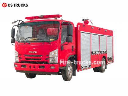
Sebagai pabrik truk pemadam kebakaran Isuzu yang paling profesional, desain inti dari truk pemadam kebakaran busa air Isuzu NPR adalah mengintegrasikan sistem pemadam kebakaran busa ke dalam truk tangki air pemadam kebakaran, membentuk peralatan pemadam kebakaran komposit yang dapat menyemprotkan air dan busa. Truk ini dapat memadamkan api secara mandiri; mengirimkan campuran air atau busa ke peralatan lain; dan cocok untuk operasi di daerah kering dan kekurangan air. ★ Teknis Spesifikasi Semua truk pemadam kebakaran dari CS Trucks, 100% berdasarkan kebutuhan pelanggan. Kapasitas Model mesin Air Busa Pompa Pemadam Kebakaran Monitor Kebakaran 2.500 liter ISUZU 4HK1 / 19 0 HP 2.500 liter 500 liter Pompa Pemadam Kebakaran CB10/40 PL8/32 Truk sasis kabin pemadam kebakaran ISUZU resmi tahun 2026 Gambar sasis truk pemadam kebakaran asli tahun 2026 Barang Detail Desain Truk Pemadam Kebakaran Isuzu Inti Desain Mengintegrasikan sistem pemadam busa ke dalam truk tangki air pemadam kebakaran, membentuk kendaraan pemadam kebakaran berkemampuan ganda yang mampu menyemprotkan air dan busa. Fitur-fiturnya meliputi: • Pemadaman kebakaran independen • Pasokan air atau campuran busa ke peralatan lain • Cocok untuk daerah kering atau daerah yang kekurangan air, memungkinkan penggunaan multifungsi. Konsep Desain Keseluruhan Dirancang untuk memenuhi kebutuhan pemadaman kebakaran di bengkel dan area sekitarnya, dengan kemampuan yang ditingkatkan untuk kebakaran minyak, listrik, dan material padat; kendaraan ini terdiri dari sasis dan peralatan bodi khusus, yang menekankan keandalan, multifungsi, dan kemudahan pengoperasian. Pemilihan Sasis • Menggunakan sasis tipe II kelas menengah atau berat yang telah teruji • Penggerak semua roda direkomendasikan untuk meningkatkan mobilitas dan traksi di medan yang kompleks. DESAIN BARU TAHUN 2026 UNTUK TRUK PEMANCING AIR ISUZU 700P Komponen Sistem Inti & Poin-Poin Penting Desain 1. Tangki Air & Tangki Cairan Busa • Bahan: Baja tahan karat, tahan korosi • Kapasitas yang disarankan: Tangki air 3000–5000L, tangki cairan busa 300–600L • Optimalisasi struktur: Sekat internal memisahkan ruang air dan busa, dapat diubah melalui port penghubung ke mode tangki air tunggal, sehingga memungkinkan penggunaan serbaguna. 2. Sistem Proporsi Busa • Menggunakan pengatur proporsi tekanan seimbang (komponen inti) untuk mencampur air dan konsentrat busa secara tepat pada rasio 3% atau 6%. • Keluaran stabil yang tidak terpengaruh oleh fluktuasi aliran atau tekanan, cocok untuk operator non-spesialis • Dilengkapi dengan saluran masuk hisap busa eksternal untuk pengisian ulang di lokasi. 3. Sistem Pembuangan • Pompa pemadam kebakaran: Pompa sentrifugal multi-tahap efisiensi tinggi dan hemat energi, laju aliran ≥ 4 0 L/S • Monitor api: Monitor serbaguna air/busa yang dikendalikan dari jarak jauh, jangkauan ≥50 meter, sudut dapat disesuaikan • Mendukung koneksi ke selang pemadam kebakaran dan nosel busa untuk pengoperasian yang fleksibel. DESAIN BARU TAH...
Detail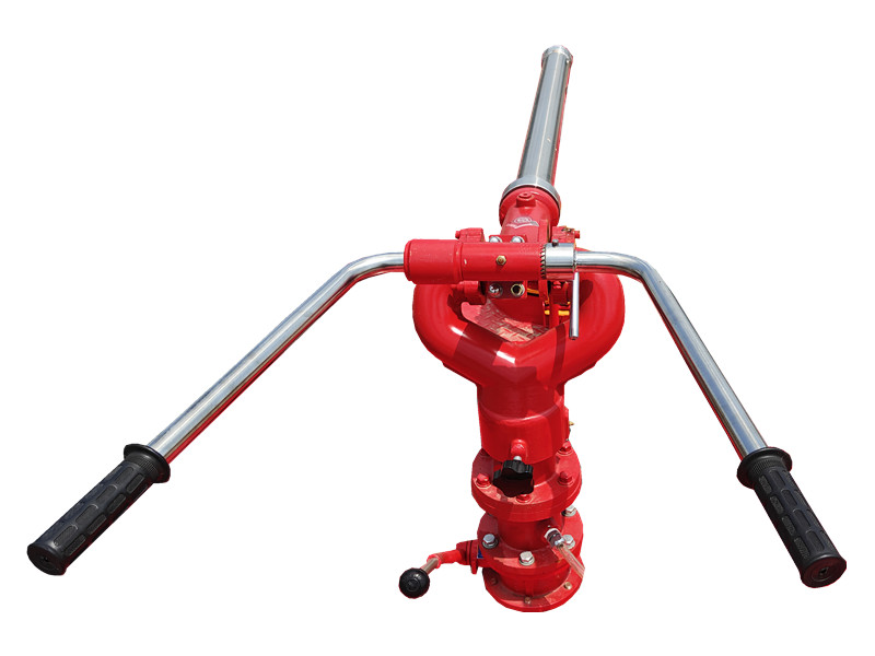
PF5-15 monitor bubuk kering tetap Menggunakan bubuk kering sebagai media dan mengandalkan alas tetap untuk penyemprotan yang stabil. Cocok untuk area kimia dan gudang, dan dapat dengan cepat menutupi permukaan yang terbakar pada tahap awal kebakaran, sehingga meningkatkan efisiensi pemadaman. Itu Monitor bubuk kering tetap PF5-15 memiliki struktur yang kokoh, mudah dioperasikan, dan dapat dihubungkan dengan sistem kontrol otomatis untuk aktivasi jarak jauh dan penyemprotan yang presisi. » Ⅰ. Monitor bubuk kering tetap PF5-15 struktur: Fitur-fitur monitor bubuk kering tetap PF5-15: ● Berfungsi penuh; ● Struktur yang sederhana dan inovatif; ● Performa stabil dan perawatan mudah; ● Tekanan masuk rendah; ● Dilengkapi dengan katup pembuangan otomatis dengan fungsi penguncian horizontal dan vertikal; ● Bahan: Paduan aluminium cor presisi; ● Kepala meriam: Paduan aluminium. » II. Meriam Busa PL24 Spesifikasi: Model Mengalir ( kg /S ) Jangkauan ( M ) Tekanan kerja terukur ( MPA ) Rotasi pitch ( ° ) Rotasi horizontal ( ° ) P×L×T ( mm ) Berat ( Kg ) PF5-15/40 40 ≥42 0,80 -45 ~ +70 0 ~ 360 980x340x550 28,5 » Ⅲ. Aplikasi Produk: Mobil pemadam kebakaran dengan monitor bubuk kering tetap PF5-15 Pengujian monitor bubuk kering tetap PF5-15 Monitor bubuk kering tetap PF5-15 memiliki jarak semprot yang panjang dan cakupan yang luas, serta dapat dengan cepat membentuk penghalang pemadam api bubuk kering. Alat ini cocok untuk lokasi tetap seperti pabrik kimia, depot minyak, dan area penyimpanan, memberikan kemampuan pemadaman api yang berkelanjutan dan stabil untuk area yang luas.
Detail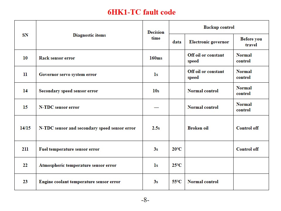
Truk pemadam kebakaran Isuzu 6HK1-TC , juga disebut Kendaraan pemadam kebakaran penyelamat Isuzu Diagnosis dan Solusi Kode Kesalahan Mesin. Mesin Isuzu 6HK1-TC menggunakan sistem kontrol elektronik pompa injeksi bahan bakar TICS yang canggih, dan ECU (Engine Control Unit) memiliki fitur diagnosis mandiri. Ketika sistem mendeteksi kesalahan, lampu peringatan "CHECK ENGINE" akan menyala dan kode kesalahan yang sesuai akan tersimpan. Memahami interpretasi dan solusi untuk kode kesalahan ini dapat secara efektif meningkatkan efisiensi perawatan mesin. Kode Kesalahan Umum dan Solusinya Kode Masalah Seri P P0101 (Sirkuit Sensor Aliran Udara Massa Rendah) Periksa sensor suhu cairan pendingin mesin dan kabelnya. Verifikasi tegangan catu daya sensor dan koneksi ground. Ganti ECU atau sensor jika perlu. P0102 (Sirkuit Sensor Aliran Udara Massa Tinggi) Periksa kualitas bahan bakar dan kondisi filter. Bersihkan sistem bahan bakar. Periksa regulator tekanan bahan bakar, pompa bahan bakar, dan sirkuit injektor. P0103 (Sirkuit Sensor Aliran Udara Massa A Tinggi) Periksa rangkaian sinyal sensor untuk kemungkinan korsleting. Uji status pengoperasian sensor. Ganti sensor atau ECU jika perlu. Kode Masalah Digital 10 (Kesalahan Sensor Rak) Periksa sensor rak dan kabelnya. Pastikan transmisi sinyal normal. 11 (Kesalahan Sistem Servo Pengatur Kecepatan) Periksa status pengoperasian sistem servo pengatur kecepatan. Uji sambungan sirkuit terkait. 14 (Kesalahan Sensor Kecepatan Tambahan) Periksa posisi pemasangan sensor kecepatan tambahan. Uji keluaran sinyal sensor. 15 (Kesalahan Sensor N-TDC) Periksa koneksi sensor N-TDC Verifikasi akurasi sinyal Pemeliharaan sistem dan tindakan pencegahan SN Item diagnostik Waktu pengambilan keputusan Kontrol cadangan data Pengatur elektronik Sebelum Anda bepergian 10 Kesalahan sensor rak 160ms Tanpa oli atau kecepatan konstan Kontrol normal 11 Kesalahan sistem servo governor 1 detik Tanpa oli atau kecepatan konstan Kontrol normal 14 Kesalahan sensor kecepatan sekunder 10 detik Kontrol normal Kontrol normal 15 Kesalahan sensor N-TDC — Kontrol normal Kontrol normal 14/15 Kesalahan sensor N-TDC dan sensor kecepatan sekunder 2,5 detik Minyak pecah Kontrol dimatikan 211 Kesalahan sensor suhu bahan bakar 3 detik 20℃ Kontrol dimatikan 22 Kesalahan sensor suhu atmosfer 1 detik 25℃ 23 Kesalahan sensor suhu cairan pendingin mesin 3 detik 55℃ Kontrol normal Konektor Terminal No. Sinyal Ukuran/diameter kawat (Kabel penghubung pompa injeksi) SWP 8 terminal Hitam 1 Tegangan penggerak aktuator governor - 1 RM 2 2 Sirkuit pengatur GND-1 W/1.2 3 Posisi rak target - 1 U1 2 4 Tegangan posisi rak G/1.2 5 Sirkuit pengatur 5V-1 Y/1.2 6 Sensor cadangan N (GND) BR/1.2 7 Sensor cadangan N (SIG) 0/1.2 8 Tarik ke bawah B/1.2 SWP6- terminal Hitam G Tegangan penggerak aktuator governor - 2 R/1.2 10 Posisi rak target - 2 L/1.2 11 Sirkuit pengatur GND-2 W/1.2 12 Sirkuit pengatur SIG-GND BR/1.2 13 Sirkuit pengatur 5V-2 Y/1.2 SWP 3- terminal Hitam 14 Pulang dengan p...
Detail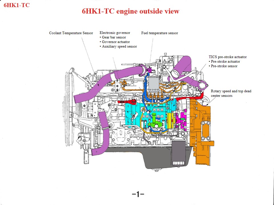
Kendaraan Pemadam Kebakaran Isuzu 6HK1 , juga disebut Truk pemadam kebakaran Isuzu , Jika mesin truk pemadam kebakaran penyelamat Isuzu mengalami panas berlebih, area-area berikut harus diperiksa terlebih dahulu: 1. Sistem pendingin: Masalah seperti kipas yang rusak, radiator tersumbat, termostat rusak, atau kekurangan cairan pendingin dapat menyebabkan mesin mengalami panas berlebih. 2. Kualitas dan kuantitas oli: Kualitas oli yang buruk atau oli yang tidak mencukupi juga dapat menyebabkan mesin mengalami panas berlebih. 3. Kegagalan mekanis seperti ledakan silinder, retakan pada liner silinder, atau kerusakan pada liner silinder juga dapat menyebabkan fenomena ini. Sebagai mesin diesel tugas berat, mesin Isuzu 6HK1 memerlukan kepatuhan ketat terhadap spesifikasi teknis untuk perawatannya. Poin-poin pentingnya adalah sebagai berikut: 1. Pemahaman Struktur dan Spesifikasi Pembongkaran dan Perakitan Mekanisme Poros Engkol-Batang Penghubung Liner silinder memiliki desain yang longgar, sehingga memerlukan alat khusus untuk mencegahnya terlepas selama pembongkaran dan pemasangan. Jarak bebas standar adalah 0,122–0,156 mm. Diameter luar piston memiliki toleransi yang ketat (114,894–114,909 mm). Selama pemasangan, perhatikan arah bukaan ring piston dan penyetelan "tiga celah" (celah ujung, celah samping, dan celah belakang). Bak engkol bawah merupakan struktur satu bagian dan harus diangkat selama perawatan untuk mencegah deformasi. Penyelarasan Sistem Pengaturan Waktu Selama perakitan gearbox, sejajarkan tanda roda gigi poros engkol dan roda gigi penegang. Tanda B pada poros bubungan harus rata dengan permukaan kepala silinder. Mesin harus berada pada titik mati atas kompresi pada silinder pertama. Saat memasang pompa injeksi bahan bakar, sejajarkan penunjuk waktu dengan titik S pada konektor, dan sejajarkan tanda pengatur waktu injeksi dengan penunjuk pada badan pompa. • Motor DC linier mendorong kumparan ke atas dan ke bawah berdasarkan sinyal keluaran unit kontrol. • Batang penghubung yang terpasang pada rakitan koil mentransmisikan gerakan naik turun koil ke blok penghubung, dan blok penghubung dipasang di ujung rak. Di bawah dorongan blok penghubung, rak bergerak ke kiri dan ke kanan untuk mengubah jumlah bahan bakar yang disuntikkan. Ketika rakitan koil bergerak ke atas, batang penghubung mendorong rak untuk meningkatkan arah aliran oli; sebaliknya, ketika rakitan koil bergerak ke bawah, rak bergerak ke arah pengurangan aliran oli, dan fungsi batang penghubung adalah untuk mengubah gerakan vertikal menjadi gerakan ketinggian rak. • Blok tembaga dipasang di bagian atas blok penghubung untuk membentuk sensor rak. Sensor rak mendeteksi pergerakan rak dan mengirimkan nilai ini kembali ke unit kontrol sehingga pergerakan rak aktual dan pergerakan rak target dapat terus dibandingkan hingga perbedaan antara keduanya mendekati nol. Proses ini sangat penting untuk mengontrol akurasi dan respons. 2. Poin-Poin Penting Pemeliharaan Sistem Sistem Pelumasan d...
Detail
Silakan baca terus, tetap ikuti perkembangannya, berlangganan, dan kami menyambut baik pendapat Anda.

 Jaringan IPv6 didukung

 Indonesia
  English
 français
 Deutsch
 русский
 italiano
 español
 português
 Nederlands
 العربية
 日本語
日本語 한국의
한국의 Türkçe
 Melayu
 ไทย
ไทย Tiếng Việt
 中文
中文 қазақ
қазақ Filipino
 မြန်မာ
 српски